Terms, definitions and characteristics
Basic definition
Crystal units are electronic devices used for the control and selection
(filtering) frequency in electronic devices. The
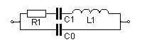
electrical perspective on the crystal unit is represented by the following equivalent
circuit of crystal resonator:
(filtering) frequency in electronic devices. The
electrical perspective on the crystal unit is represented by the following equivalent
circuit of crystal resonator:
Other terms and definitions
| Term | Ref.symbol | Definitions |
|---|---|---|
| Motional resistance | R1 [Ω] | The resistance in series arm of the equivalent circuit. It represents energy losses of vibrations in the resonator. |
| Motional inductance | L1 [mH] | The inductance in series arm of the equivalent circuit. It represents mass inertia of the resonator. |
| Motional capacitance | C1 [fF] | The capacitance in series arm of the equivalent circuit. It represents elasticity of the resonator. |
| Shunt capacitance | C0 [pF] | The capacitance in parallel arm of the equivalent circuit. It represents the resonator as a capacitor at frequencies outside the resonance |
| Quality factor | Q | Dimensionless parameter characterising losses of vibration energy in resonator |
| Capacitance ratio | r | The ratio of shunt capacitance to motional capacitance, wich determine some characteristic features of crystal units |
| Motional (series) resonance frequency | fs [kHz, MHz] | The frequency at which the conductivity reaches a maximum |
| Parallel resonance frequency | fp [kHz, MHz] | The frequency at which the resistance reaches a maximum. |
| Resonance frequency | fr [kHz, MHz] | The resonant frequency is the lower of two frequencies of the crystal unit itself, in specific terms, the electrical impedance of the crystal unit is resistiv |
| Anti-resonance frequency | fa [kHz, MHz] | The anti-resonant frequency is the higher of two frequencies of the crystal unit itself, in specific terms, the electrical impedance of the crystal unit is resistive |
| Working frequency | fW [kHz, MHz] | Working frequency is the operational frequency of the crystal unit together with associated circuits |
| Load resonance frequency | fL [kHz, MHz] | The resonant frequency with load capacity in which the electrical impedance of this combination is resistance. |
| Load capacitance | CL [pF] | External capacitance associated with the crystal unit which determines the load resonance frequency fL. |
| Load resonance resistance | RL [Ω, kΩ, MΩ] | The resistance of the crystal unit in series with the capacity for external frequency fL. |
| Fractional load resonance frequency offset | DL | The relative change in resonant frequency caused by connecting the load capacity CL of the crystal unit |
| Fractional pulling range | Frequency change, caused by the load capacity value of CL1 to CL2. | |
| Pulling sensitivity | S | Partial resentment as a function of change in the load capacity of 1 pF at the designed load capacity CL. |
| Operating temperature range | [°C] | The range of temperatures over which the crystal unit shall be within the specified tolerances |
| Operable temperature range | [°C] | The range of temperatures over which the crystal unit will not sustain permanent damage though not necessarily functioning within the specified tolerances |
| Storage temperature range | [°C] | Minimum and maximum temperatures, at which the crystal unit may be stored without deterioration or damage to its performance |
| Reference temperature | [°C] | The temperature at which crystals are measured. For the termostated units is the reference temperature in the middle range of the thermostat. For non-termostated units is the reference temperature usually 25°C ± 2°C |
| Frequency tolerance | [ ppm ] | Maximum permissible deviation of the working frequency caused by a cause or a combination of causes |
| Level of drive | [ µW] | Level of drive is a measure of the conditions imposed upon the crystal unit. This may be expressed in terms of current through or power dissipated in the crystal element |
| Drive level dependency | ( DLD ) | Drive level dependency is the effect of changes in drive level conditions upon the resonance resistance or frequency of the crystal unit. This parameter can be specified by defining the ratio of resistance between two specified drive levels, or max. relative resistance and/or frequency change over specified drive level range. |
| Activity dip | Undesirable changes in the resistance R1 | |
| Frequency dip | Undesirable changes in the frequency fL. This change is usually related to the change in R1 and depend on CL and level of drive | |
| Hysteresise | Hysteresis is the max. fractional frequency difference between two crystal unit frequency measurements at reference temperature (25 °C ± 3 °C) before and after passing through full operating temperature range. |
|
| Long-term frequency stability (aging) | The maximum permissible change in resonant frequency crystal units for a defined period (usually a year) at constant external conditions (temperature, drive level, etc.) |
|
| Short-term frequency stability | Random fluctuations in the resonant frequency of crystal unit in short time interval |
Reference
For more information about the parameters of crystal units and their measurement
can be obtained from the following technical standards:
EN (IEC) 60 122-1, Quartz crystal units of assessed quality – Part 1: Generic specification
EN (IEC) 60 444-1 to 6, Measurement of quartz crystal unit parameters
EN (IEC) 60 444-1 to 6, Measurement of quartz crystal unit parameters
Information on the practical use of crystal units is described for example in
EN (IEC) 60 679-1, Quartz crystal controlled oscillators of assessed quality